Circuit Diagram Of Vfd Panel Vfd Diagram Ac Drives Wiring Mo
Vfd plc ladder logic frequency instrumentationtools circuit controller scada [diagram] abb vfd control wiring diagram Vfd controlled by switches
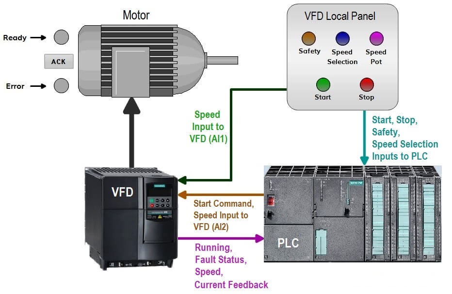
How to Control VFD with PLC using Ladder Logic
Vfd frequency trainer [diagram] abb vfd wiring diagram free picture schematic Inside variable frequency drive (vfd) panel: configuration, schematics
Vfd wiring schematic
Variable frequency drive 3 phaseWiring diagram for vfd How to control vfd with plc using ladder logicVfd ac diagram drive block drives electric electrical dc typical frequency control electricaltechnology parts basic construction working difference variable converter.
What is a vfd?Vfd control wiring diagram Inside variable frequency drive (vfd) panel: configuration, schematicsVfd (variable frequency drive).
Vfd wiring diagram probotix huanyang instructions wiki spindle wire speed power controller 10v output board contact pixels original mill
What is variable frequency drive circuit: its operation, types andBasics and common applications of vfds Vfd wiring diagram with motor, switches, and external devicesVfd circuit drive types operation working gupta sourav jan.
Vfd plc ladder logic variable scada instrumentationtools advantages centerWhat is ac drive? working & types of electrical drives & vfd Wiring diagram for vfdHow to make a 3 phase vfd circuit – homemade circuit projects.

Vfd panel wiring diagram
Control wiring for variable frequency drives (vfds)Circuit vfd phase diagram controller pwm voltage homemade make circuits Wiring connection inverter vfd logic genus relayVfd wiring instructions.
Vfd bypass dol starterVfd (variable frequency drive) Vfd diagram ac drives wiring motor operation panel circuit variable frequency principles drive schematic dc inverter phase 3phase vsd convertVfd diagram plc wiring control circuit schematic drive using ladder diagrams connections make logic.
Vfd variable speed motor drive ac diagram installation block switches controlled control frequency connected function phase drives controller terminals components
[diagram] electric motor wiring diagram rectifierFile:vfd wiring diagram.jpg Inverter drive motor connectionVfd wiring schematic.
Vfd motor control circuit diagramVfd circuit diagram explanation How to control vfd with plc using ladder logicVfd schematic diagram and control.

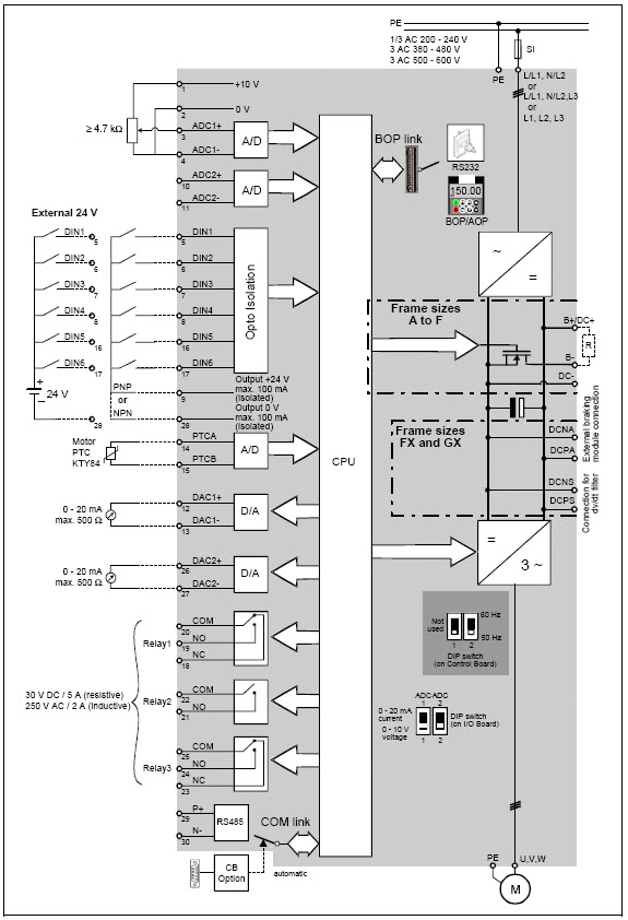
Circuit diagram of vfd panel
Vfd circuit diagram explanationWiring diagram vfd c17 manual file probotix wiki july Vfd panel wiring diagram gallery.
.


