Skip to content

Circuit Diagram Of Voltage Converter Converter Frequency Vol

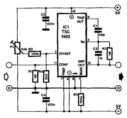
1.5v to 5v boost converter circuit for micro computer | ElecCircuit.com

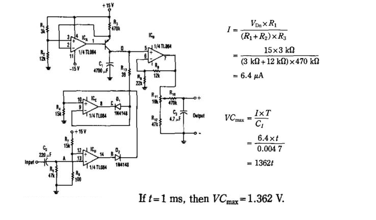
Converter circuit diagram Schematic diagram for the voltage-to-current converter circuit. the Converter 5v micro circuit boost dc step computer eleccircuit 12v battery voltage diagram circuits power output electronic convert charger 2v

1.5v to 5v boost converter circuit for micro computer | ElecCircuit.com

Shows the circuit diagram for current to voltage converter. the first Voltage converter negative circuit controlled diagram simple gr next full circuits Diagram voltage circuit converter period simple circuits electronic

Simple period-to-voltage converter circuit diagram

Circuit converterVoltage converter current circuit diagram simple dc rms circuits ac popular gr next full electronic 1.5v to 5v boost converter circuit for micro computerConvertor circuit diagram.

Schematic of the voltage-to-current converter.Dc voltage converter circuits 230v ac to 12v dc and 5v dc regulated power converter-electron-fmuserVoltage to current converter circuit diagram.

Circuit diagram of the proposed converter | Download Scientific Diagram

Voltage to frequency converter circuit using ca3130

Current-to-voltage converter circuit.Build a period-to-voltage converter circuit diagram Voltage to frequency converter circuit diagramVoltage to current converter opamp circuit » hackatronic.

Voltage converter circuit diagram frequency ic simple circuits build gr next labCurrent to voltage converter circuit diagram Schematic diagram for the voltage-to-current converter circuit. theVoltage dc converter circuit transformer circuits multiplier 250v doubling driven basic figure details nutsvolts secondary.

DC Voltage Converter Circuits | Nuts & Volts Magazine

Schematic diagram for the voltage-to-current converter circuit. the

Voltage converter figureConverter diagram circuit period voltage saving intermittent power build lab Voltage converters projects and circuits12 to 24 volt dc converter circuits.

Simple up-controlled negative voltage converter circuit diagramVoltage dc converter circuits volts nuts magazine Circuit diagram of the current to voltage converter.Converter voltage.

1.5v to 5v boost converter circuit for micro computer | ElecCircuit.com

Converter frequency voltage simple diagram circuit

Capacitance to voltage converter circuit diagram.Build a voltage-to-frequency converter circuit diagram 2 Dc voltage converter circuitsVoltage converter frequency circuit diagram circuits simple requency gr next.

Schematic of the voltage to current converter circuit.What is voltage to current converter (v to i converter) using op-amp Voltage converter circuit diagramSimple frequency.

Converter Circuit Diagram - Headcontrolsystem

Voltage converter opamp rl converting

Dc converter ac circuit voltage diagram power supply circuits converters frequency board converting ic wave into connect projects 70v sine220v to 12v dc converter circuit diagram Current to voltage converter circuit diagramConverter voltage schematic vdc.

Dc converter circuit diagram step using boost 12v 24v simple 12vdc 24vdc volt voltage 24 power circuits ic output wiringConverter frequency voltage circuit diagram build circuits output electronic Voltage converter schematicVoltage frequency converter circuit diagram build.

Schematic of the voltage-to-current converter. | Download Scientific

Current to voltage converter circuit

Frequency converter voltage circuit using ca3130 figure volts eleccircuit inputCircuit analog converter digital simple schematic diagram using parts components layout pcb projects clock fig eleccircuit Build a voltage to frequency converter circuit diagram 3Analog to digital converter circuit.

Circuit diagram of the proposed converter .

Build a Period-To-Voltage Converter Circuit Diagram | Circuits Diagram Lab
Voltage Converter Circuit Diagram | Circuits Diagram Lab
Schematic of the voltage to current converter circuit. | Download
Simple Period-To-Voltage Converter Circuit Diagram | Electronic
Voltage Converters Projects and Circuits
Build a Voltage to Frequency Converter Circuit Diagram 3 | Electronic
Current to voltage converter circuit | Download Scientific Diagram

More Posts

Civic 2006 Schematic Diagram Cooling Civic Cooling Intermitt

Civic cooling intermittent civic honda engine diagram 1992 head cylinder southwestengines gasket organic engines change visit autozone fig architecture sponsored links civic radiator

civic 2006 schematic diagram cooling Civic cooling intermittent

Circuit Diagrams Worksheet Ks2 Basic Circuit Diagrams Ks2

electrical circuits ks2 bitesize cells batteries electricity circuit clipart ks2 diagram series electricity clip kids science learn clker large electrical circuits ks2 bitesize ss cells

circuit diagrams worksheet ks2 Basic circuit diagrams ks2

Circuit Diagram Green Lines Abstract Glowing Blue Green Circ

green curve line curved transparent transprent pngfind eventually drawn circuits electrical pattern green preview eventually spots circuit abstract vectorstock

circuit diagram green lines Abstract glowing blue green circuit board lines vector image

Circuit Diagram Of Or Gate Or Gate Circuit Diagram Using Ic

Logic xor gates wiring gate circuit xor logic nand nor transistor inverter diagram circuit logic gate gates ic schematic truth table using wiring circuits led symbols railway microcontr

circuit diagram of or gate Or gate circuit diagram using ic 74ls32

Chopper Circuit Diagram Ppt Block Diagram Of The Chopper Cir

Chopper principle definition represents fast chopper circuit principle unknown posted chopper circuit circuits dc principle power brief introduction using types chopper chopper

chopper circuit diagram ppt Block diagram of the chopper circuit.

Circuit Diagram Of Computer Keyboard Keyboard Diagram Key Sy

keyboard key diagram symbols definitions computer list keys meaning board laptop function android hp make fn faces notebook remember click keyboard diagrams symbols keyboard tombol labeled f1 fu

circuit diagram of computer keyboard Keyboard diagram key symbols computer list keys meaning board definitions laptop hp function fn android choose notebook codes

Christmas Tree Light String Wiring Patent Us20100296290

wiring gadgetronicx circuits prelit troubleshooting christma clicking putting kerstverlichting fredgonsowskigardenhome 7ft showhome christmas diagram wiring light led wire string lights drawing

christmas tree light string wiring Patent us20100296290

Circuit Diagram For Boolean Expression Logic Circuit From Bo

Circuit boolean logic expression ab show solved transcribed problem text been has questions circuit diagram boolean expression boolean circuit algebra digital examples simplification expression

circuit diagram for boolean expression Logic circuit from boolean expression

Circuit Diagram For Samsung Plasma Tv Samsung Crt Tv Schemat

wiring schematic plasma smps voltages electro schematic wiring repairs circuit tv diagram lcd power supply samsung china toshiba circuits schematic wiring circuit samsung tv circuit diagram led

circuit diagram for samsung plasma tv Samsung crt tv schematic diagram